It has been interesting to see how our project has progressed over the semester from Dharawan's initial concept to the creation of the paintMotion. The product has really become each of our's slowly over the semester as we each put in our own individual ideas and research.
As the object person I really enjoyed working with the form, function and aesthetics of the product and how they fit in with the scenario and the behaviour. At times it was challenge because I didn't have a great idea of what technology to use. I did however learn a lot this semester about the technology side of the product and I hope to keep growing on that knowledge.
As a social telepresence project, I believe that we have created a product that really would help with communication and relationships between people such William and other painters. It encourages its users to do something productive, stimulating and cultivating interaction between other users.
Along with doing the cad work for the project, I also got to make a model in the workshop and I found that I really enjoyed the opportunity to actually make something. It was a good learning experience as I haven't had much of an opportunity to do that before. This was all made so much easier as well by Claire and Dharawan providing great scenarios and behaviours that really influenced how the product was designed.
Even though this product does not solve a problem as such, it enriches the activity of painting, mainly due to the interaction with the actual product and the other painters in their community/ following. The users interaction with the product is vital to its success and how it works.
What I love about our product is that I can see it actually being made and being really enjoyable to own and use.
Monday, November 7, 2011
Friday, November 4, 2011
final boards


Wednesday, October 26, 2011
solidworks images
 |
| Final water pot assembly image. |

The pot will sit on the center of the base with a series of LED's around it. The weight of the glass and the wide opening makes sure that the pot is stable while still rotating in response to the painters. The rubber dials one the side are there for the users to choose who they are sending and receiving to.

The base has a 1mm recess in the top of it so that it is flush with the curved edges of the base.This recess has been painted white so that the light reflected is pure and allows for the users to see more of the colour that is output. The top of the base also has recesses for the wheels and for the servo motor.

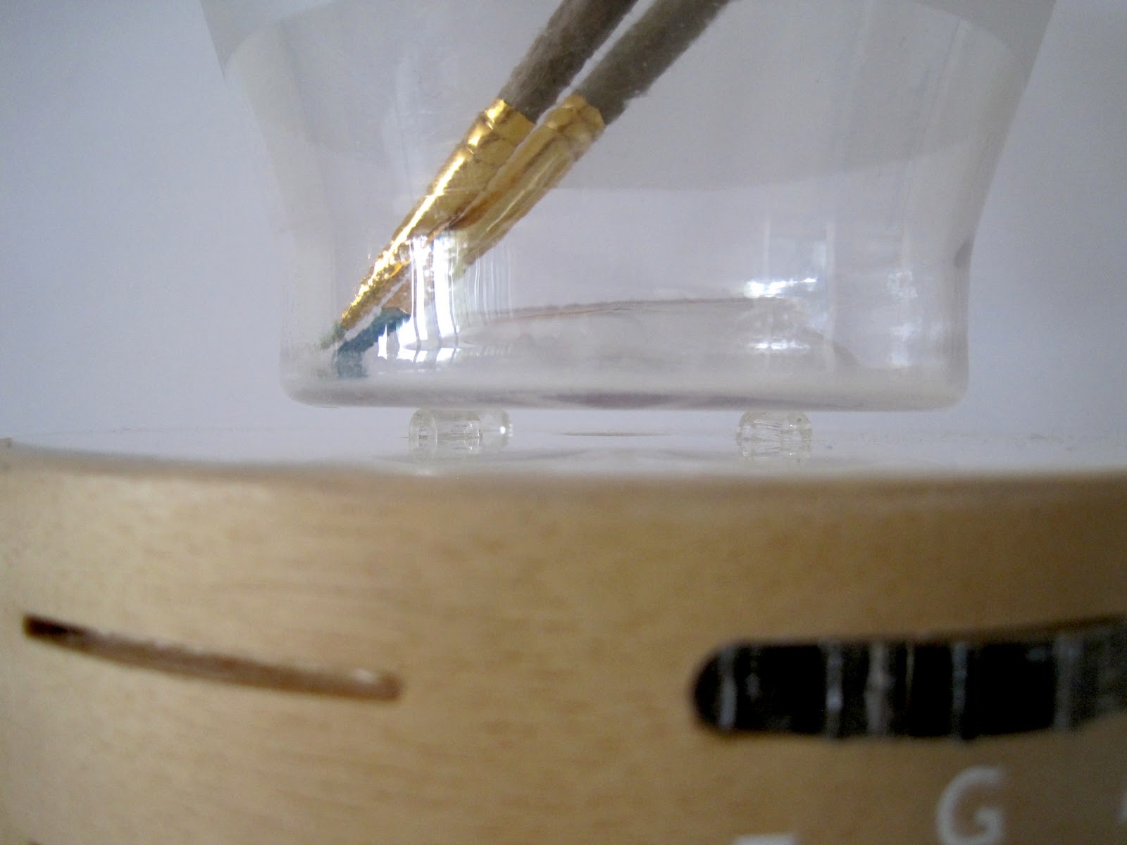
Borosilicate glass will be used for the pot for multiple reasons. One is that is has a great clarity and reflective value which is hard to get with a lot of plastics. Also painters use different cleaning agents according to the type of paint they use and some of these would damage a plastic pot. Therefore we decided on glass and it also give the product a sense of quality and durability. The pot will be manufactured by pressing due to the shape of the pot. The outside top section of the pot will be sand blasted to allow the pot to glow if not moving as can be seen here.

Wristband design one. The band is coated in white silicone. It can be wiped down after using it and therefore the way it is assembled will ensure it is water resistant.

The two parts of this design allow the user to change the batteries whenever they want. The fact that it sits so far into the band it means that it will be water resistant. This silicone band has mild steel inside so that each user can squeeze the band onto the users arm.

I redesigned the wristband because i wasn't really happy with the previous solution. As can be seen in the above image, the previous band was in two parts and i'm not sure it would have been suitable to every user. This new wristband is really simple, like the rest of the product and it also can be put on with one hand. It also ensures that it fits any size wrist. The end of the band has a cap that can be removed and then plugged via usb into the computer to recharge.
Tuesday, October 25, 2011
base model part 2
The base of the product was cut from a larger piece of wood and then trimmed with a bandsaw. After getting the rough shape, we then used the lathe to cut down the edges to a precise smooth shape.

The internal void and the top recess were cut out with a router to precise measurements also.

As can be seen above, the top of the base has a 1mm recess in which the glass plate sits in. This can be seen in the image below. This recess is also painted white rather than painting the glass.

In reality, these cog dials above will be made from white rubber however for the model, I used laser cut acrylic.

This shows that the pot sits in the centre of the base and shows where the rotor will sit within the pot.

The wheels are set into the glass plate to take the weight of the pot off the servo motor.


This shows where the cog wheels will fit in within the internal recess.
Monday, October 24, 2011
base model
The modelling of the base was all from a piece of wood. We had to do two bases because the first one flew off the lathe at one point and took a chuck out of it.
Firstly we cut a section from a plank of wood in the workshop. I had to bandsaw the edges off to give it a rough circular shape. To get the exact shape, we then lathed the rest of the outer wood off and then also sanded it on the lathe. This gave us the basic cylindrical shape and then we had to put in the recess in the top and internally. The base has a 10mm wall and the top also has a 10mm thickness.
To machine out the internal part, Maurie machined it out with the router as can be seen below. This gave us a precision cut and finish. We then cut out the holes on the side for the cog dials and for the light indicators and the acknowledgment button on the same router. We also drilled the light tubes at this time.
The process would be much quicker in a mass produced scenario as machines would be set up to do a large amount of the cutting and finishing of this part.


Saturday, October 22, 2011
wristband modeling
I wanted to make a wristband to work out how it works and how it feels in relation to the pot and base. I started off with a plastersine to model the shape off the band.

I then made up some plaster in order to create a mould for a silicone casting. Plaster was fine because the design had a flat base and therefore a one sided mould was fine.

I stirred up some plaster powder and water to make the paste.

Before the plaster set, i pressed the plastersine model into the paste so the it was level with the surface.

After sitting for about 20 minutes, the plaster dried and I was able to remove it from the container.


I could then peel it out of the plaster which left behind a pretty good mould.

I then had to mix up the two agents for the silicone. This had to be done really quickly because it goes off in about 6 minutes.


Then all I had to do was poor it slowly into the mould so that it didn't get any bubble and stick to the plaster.

The top one is the first silicone band from the first mould. I did another mould with a slightly different shape and I also put two thin wires inside the silicon. This allows me to bend it or squeeze it onto a wrist. The bottom one is two acrylic parts that I dipped in the silicone. This worked ok but it peels off quite quickly.

pot modelling
As our water pot is made from glass in real life the pot will be pressed. Seeing that we couldn't do that in real life, we decided to make the pot out of plastic for presentation purposes. The process can be see below.

The mould was made from mdf boards glued together and then carved with the lathe to the right shape. The mould is also extended past the size of the pot so that the mould can be removed after it is moulded.

The top was then cut out with a router for the servo rotor. The whole mould was then sanded so that the particles and marks don't show up in the plastic. We drilled ventilation holes in the centre and corners so that the plastic was sucked into the cutout.

The plastic was then heated up and placed over the mould so that the plastic is sucked onto the mould.

As you can seen, this took a few times because the difference speeds that the vacuum was turned on and brought down on the mould creased the plastic.

After the mould was right, i cut the top off with a bandsaw and wet sanded the edges.

The pot was then sandblasted by taping the bottom, so that the bottom was left clear.

This pot was the clearest mould but the cutout was still a little rounded.

The rounded edges can be see above.

This pot has a more defined and sharp cut out however it was more cloudy and the lines from each mdf pieces are on the plastic.

Subscribe to:
Comments (Atom)